

How To Change King Pin On Front End Of An 2014 Ezgo Golf Car
MAINTENANCE
Routine maintenance of the front suspension and steering consists of:
• periodic inspections for loose, worn or damaged components
• alignment checks
• lubrication of ball joints and bicycle bearings
Be sure to employ simply the recommended lubricants. Maintain the correct adjustment of the front bearings and repack them in accordance with the Periodic Service Schedule or if a bearing replacement is required. Routine exam of the tires volition provide indications if an alignment is required.
Lubrication
Grease the rack ball joint. Wipe off former grease that is forced out of rubber kick.
Wheel Bearing and King Pivot Bushing Inspection
Lift the front of the vehicle and support on jack stands. Rotate the front bike and feel for any roughness. While property spindle with one paw, grasp bottom of tire with other hand and stone tire back and forth on spindle.
If excess movement is detected, the wheel bearing may require repacking and adjusting or replacement. If the wheel bearing is satisfactory, a worn spindle bearing, which is not a serviceable particular, is indicated and the spindle must be replaced.
Wheel Bearing Packing
Remove hub from spindle and detach. Clean all bearings, grease seal, hub and grit cap in solvent and dry thoroughly. Inspect for signs of damage. Pitting or a blue coloration of the rollers will require replacement of the bearing. If the roller portion of the bearing is to exist replaced, the race must also be replaced.
The front wheel bearings are tapered roller type and must be packed with grease at installation or any time the bearing is removed for inspection. Information technology is recommended that a bearing packer fastened to a grease gun be used; all the same, transmission packing is acceptable if done correctly. To pack a bearing manually requires that a dab
of grease be placed in the palm of the hand and the bearing be dipped in the grease. Force the grease upwards through and around all of the rollers until the unabridged bearing is saturated in grease. Gather hub and install on spindle.
Cycle Bearing Adjustment
If performing a wheel bearing adjustment just, elevator and support front of vehicle. Remove dust cap and cotter pin and loosen castellated nut.
If performing a bicycle bearing adjustment as function of another procedure, make certain wheel is mounted to hub hand tight with lug nuts and hub is loosely retained on spindle with castellated nut. Seat bearings by rotating wheel while tightening castellated nut until slight resistance is felt. Rotate the bicycle 2 – iii more turns to readapt backlog grease. If required, tighten castellated nut once more until slight resistance is felt. If the cotter pin hole in the spindle aligns with a slot in the castellated nut, insert a new cotter pin. If the hole does not align, the castellated nut must be loosened to align with the closest available slot in the nut.
Check for polish and free rotation of the cycle and an absence of play when the wheel is grasped past the exterior of the tire. Bend the cotter pin against the flats of the castellated nut. Supervene upon the dust cap and lower vehicle.
Cycle Alignment
Lift the front of the vehicle and support on jack stands. Confirm the alignment of the front springs. Rotate each wheel and scribe a chalk line effectually the circumference of the tire at the center of the tread pattern. Lower vehicle and, with tires in the directly ahead position, roll it frontwards approximately 5 feet in order to let the tires to have their normal running position. Measure the distance between the chalk lines at both the front and rear of the tires The measurement taken at the front of the tires should exist 0″ – ane/8″ (0 – iii mm) less than the rear.
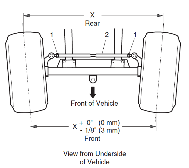
To adjust cycle alignment, loosen tie rod jam basics and turn tie rod until correct alignment is accomplished. Tighten jam nuts to 36 – 40 ft. lbs. (49 – 54 Nm) torque.
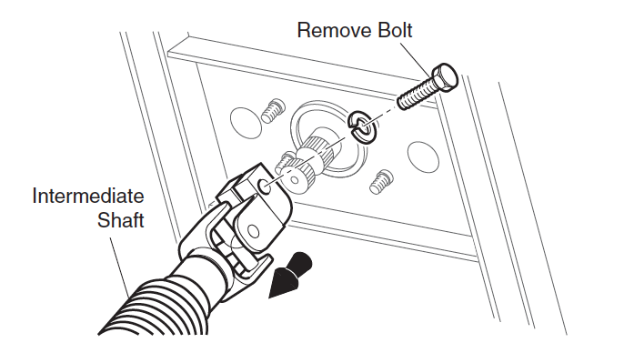
Test drive vehicle and confirm steering bicycle is correctly centered. If information technology is non centered, disconnect intermediate shaft from steering shaft and center steering wheel. Reconnect intermediate shaft and tighten commodities to 155 – 215 in. lbs. (18 – 25 Nm) torque.
Front Shock Cushion Replacement
Remove the nut from the lesser of the shock absorber at the front axle. Shrink daze absorber to clear the mounting bracket.
Loosen the nut securing the tiptop of the shock absorber to the vehicle frame and so rotate the shock absorber while property the nut in identify with a wrench. Remove the shock cushion. Installation of shock cushion is reverse of disassembly. Mounting basics should exist tightened until safe bushings expand to bore of shock absorber washers.
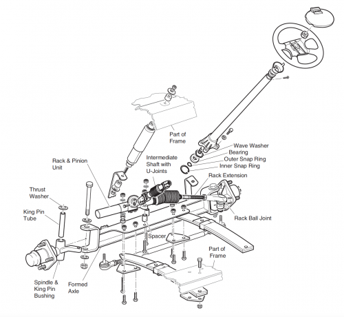
Front Beam Replacement
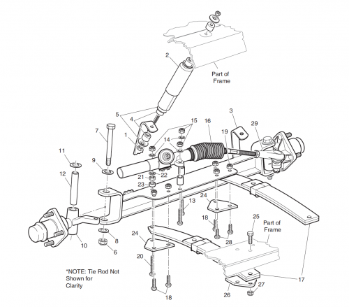
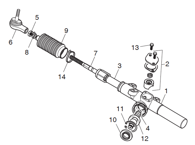
Remove front wheels. Remove fittings securing the shock absorbers to front axle. On the commuter side, remove lock nut and washer from bolt and discard nut. Pull bolt and washer from spindle and separate spindle from axle. Remove thrust washer and king pin tube from spindle, wrap towel around spindle and allow spindle rest on ground. Repeat at passenger side letting rack ball joint residual on front bound to support spindle. Remove hardware securing rack and pinion unit to front beam and discard lock basics. Move rack and pinion unit of measurement back to rest on elevation of forepart springs. Secure rack and pinion unit to spring with wire to preclude pulling apart intermediate shaft. Remove the three 1 iii/four″ long bolts, 2 i 1/2″ long bolts, spring plate and 5 lock basics securing axle to springs and discard lock nuts.
At the 3 one/2″ long commodities securing front end of left jump, note location of washer and remove it from end of bolt. Remove nut, 3 1/ii″ long bolt, spring plate and spacer and retain them for assembly at their original locations.
Front axle installation is the opposite order of disassembly using new lock nuts. All hardware must be installed in its original location. Tighten leafage bound and rack and pinion unit hardware to 35 – 50 ft. lbs (50 – seventy Nm) torque. Install thrust washers, king pin tubes, spindles, washers and bolts. Tighten new lock basics to 56 – 70 ft. lbs. (75 – 95 Nm) torque. Bank check that spindle turns freely on rex pin tube later on tightening.
Tighten shock cushion mounting hardware until rubber bushings aggrandize to diameter of shock absorber washer. Bank check front end wheel alignment and arrange if necessary.
Front Jump Replacement
The following procedure will replace one spring at a Time. Loosen front end wheels. Lift and support front of vehicle. In addition, support front axle with jack stands. Remove forepart wheels.
To detach driver side bound:
Fully loosen the ii rack and pinion unit of measurement lock nuts, one near the bellows and ane on the rear side of the rack and pinion unit, until only one thread is engaged. Remove the lock nut and washer from the long bolt and discard lock nut.
The rack and pinion unit is at present loose. Remove the two one 3/iv″ long bolts and lock nuts securing driver side spring to axle and discard lock basics.
Hold nut with wrench and loosen long commodities. Annotation location of washer and thread long bolt out as far as possible to remove the washer, nut and spacer. Then pull long bolt and spring plate (24) from axle and spring. Retain above items for assembly at their original locations. Pull upper commuter side of flooring mat out of plastic trim retainer and away from floor. Locate and remove hardware securing rear of spring to vehicle frame and discard lock basics.
Driver side spring installation is the contrary club of disassembly making sure to install the long bolt, spring plate, spacer, nut and washer in their original locations. Utilize new lock nuts to secure the rack and pinion unit, two short bolts and rear bolts.
To detach passenger side spring:
Remove the hardware securing the front of the passenger side leaf leap to the axle and discard lock nuts.
Pull upper passenger side of floor mat out of plastic trim retainer and away from floor. Locate and remove hardware securing rear of jump to vehicle frame and discard lock nuts.
Using new lock basics, install passenger side bound in the reverse social club of disassembly.
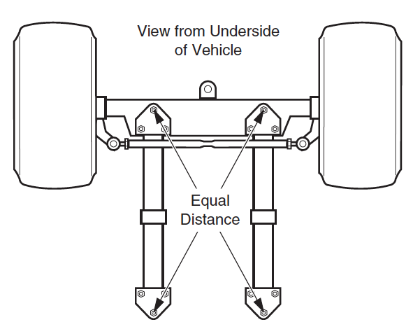
When front end springs are replaced, the front axle must be aligned to the frame. The distance from the center bolt at rear of left spring to the center bolt at front of correct spring must exist the same equally the distance from the centre bolt at rear of right leap to the centre bolt at front of left spring. Tighten the leap hardware first and rack and pinion unit hardware next to 35 – 50 ft. lbs. (50 – seventy Nm) torque.
Supercede upper portion of floor mat in plastic trim retainers. Install front wheels and lower vehicle. Bank check front end wheel alignment and adjust if necessary.
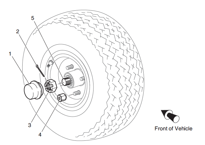
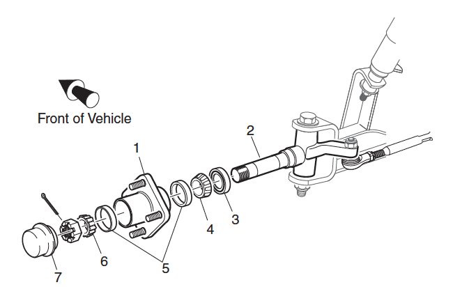
Hub Replacement
Loosen front bicycle(s). Lift and back up front of vehicle and remove forepart bicycle(s).
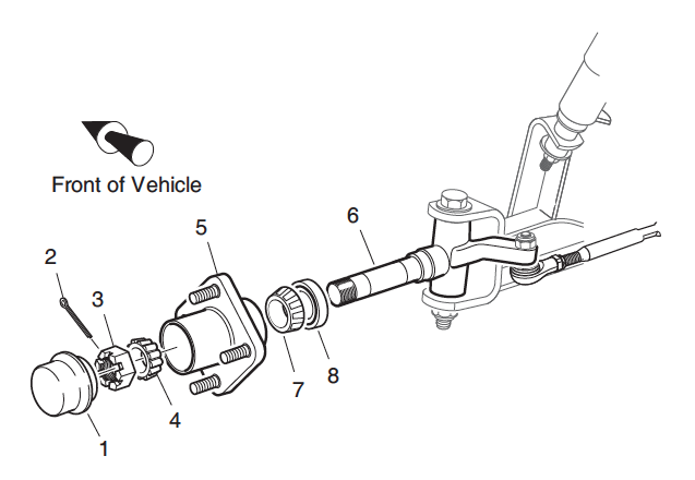
Remove the dust cap, cotter pin and castellated nut. While property outer wheel bearing in identify, slide hub from spindle and discard.
Make clean spindle and new hub thoroughly with solvent. Pack new bearings with grease.
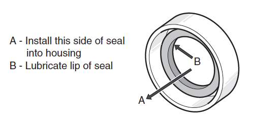
Utilise a low-cal coat of grease to inner race and place inner cycle bearing in hub. Orient new grease seal so the flange side of the seal is facing into the bore. Tap gently into identify until seal is flush with stop of hub. Lubricate lips of seal and spindle with grease.
Place new hub onto spindle and fill the area between the two wheel bearings about i/ii – iii/four total with grease and apply a low-cal coating to the outer bearing race. Install outer wheel bearing and secure hub loosely with castellated nut. Identify bicycle onto hub and paw tighten lug nuts. Adjust bearing. Replace the dust cap. Lower vehicle and tighten front end bike(south).
Wheel Bearing and Race Replacement
Remove hub from spindle. Remove the grease seal, inner wheel bearing and bearing races by tapping, through the other side of hub, the bearing race using a hammer and a soft nonferrous punch. Tap race in a circular design while moving from side to side to avoid dissentious diameter of hub.
Clean outer bike bearing, inner wheel bearing, hub and dust cap in solvent and dry thoroughly. Inspect for signs of damage. Pitting or a blue coloration of the rollers requires replacement of the bearing. If the roller portion of the bearing is to exist replaced, the race must also be replaced. To install race, make sure bore of hub is make clean and place new race over bore of hub. Evenly tap with hammer and bearing commuter to drive race fully in bore. Repeat on other side of hub. Clean spindle and pack new bearings with grease.
Install inner bike begetting and new grease seal in hub and mount hub to spindle.
Conform bearing. Supplant the dust cap. Lower vehicle and tighten front end wheel(southward).
Rack Ball Joint Replacement
To remove rack ball joint, loosen passenger side front bicycle and elevator and support front of vehicle. Remove passenger side front end wheel and plough steering cycle fully to the left. Remove the cotter pin and loosen the castellated nut until rack ball articulation threads are protected. Using a ball articulation separator as a lever, utilize pressure to brawl articulation and tap nut with plastic faced hammer to release ball joint from passenger side spindle arm. Remove nut from ball joint and brawl joint from spindle arm.
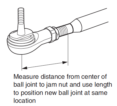
To install new rack ball joint close to its correct position, measure corporeality of threads exposed from jam nut.
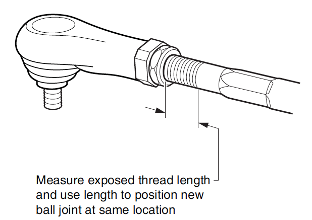
Loosen jam nut and remove rack ball joint from rack extension. Using measurement fabricated earlier, thread jam nut and new rack ball joint to previous location on rack extension and set up jam nut hand tight. Attach rack brawl joint to spindle arm. Tighten castellated nut to 36 ft. lbs. (50 Nm) torque and continue to tighten equally needed to insert new cotter pivot. Maximum torque is 50 ft. lbs. (70 Nm).
Check for proper rack extension-to-rack and pinion unit clearance before tightening jam nut to 35 – 45 ft. lbs. (47 – 61 Nm) torque. Install passenger side front end wheel.
Cheque front wheel alignment and accommodate if necessary.
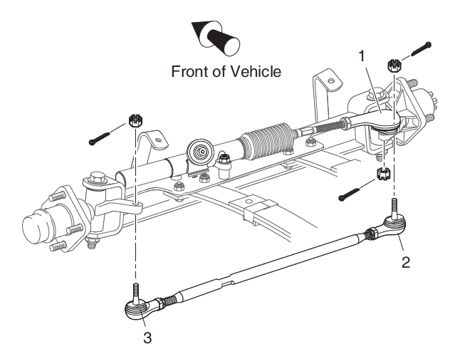
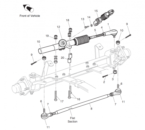
Necktie Rod Inspection/Replacement
Grasp the tie rod at brawl joints and check for any vertical movement which would betoken a worn status and require replacement. To remove necktie rod, loosen wheel(s) and lift and support forepart of vehicle. Remove front bike. To install new tie rod ball joint close to its correct position, measure out distance to center of ball articulation from jam nut.
Remove cotter pin and loosen castellated nut until tie rod ball articulation threads are protected. Using a ball joint separator as a lever, apply force per unit area to brawl articulation and tap nut with plastic faced hammer to release necktie rod from spindle arm. Remove nut to drop tie rod from spindle arm. Unscrew tie rod ball joint and jam nut from threaded tube.
To install ball joint, first thread on new jam nut then, using measurement made earlier, spiral ball articulation to previous location in threaded tube. Set jam nut manus tight.
Install rubber boot and adhere tie rod to spindle. The castellated nut should exist tightened to a minimum of 36 ft. lbs. (fifty Nm) torque and go on tightening as required in order to insert a new cotter pin. Maximum torque is fifty ft. lbs. (70 Nm).
A worn tie rod is likely to accept caused wrong bicycle alignment. Check front wheel alignment and suit if necessary. Jam nut should be tightened to 36 – twoscore ft. lbs. (49 – 54 Nm) torque.
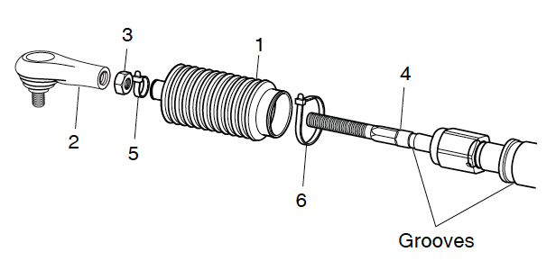
Bellows Replacement
To replace bellows, first loosen passenger side forepart bicycle and lift and back up front end of vehicle. Remove passenger side front bicycle and plough steering bicycle fully to the left. Remove rack ball joint and jam nut from rack extension. Cutting wire ties and slide bellows off rack extension. Install new bellows aligning small cease over groove in rack extension and secure with new wire tie. Go out large end loose until rack extension-to-rack and pinion unit clearance is checked or adjusted. Install jam nut and rack brawl articulation on rack extension and reattach to spindle arm.
Check for proper rack extension-to-rack and pinion unit clearance before tightening jam nut to 35 – 45 ft. lbs. (47 – 61 Nm) torque. Install rider side forepart cycle and lower vehicle. Cheque forepart bike alignment and adjust if necessary.
Pinion Seal Replacement
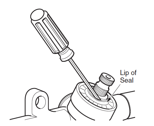
To access the pinion seal, remove rack and pinion unit from vehicle. Ballast in vice by clamping on the mounting ears of the rack and pinion unit. Slide a pocket-size directly bract screwdriver between lip of seal and pinion and pry elevation portion of seal up to remove. Utilise screwdriver to lift inner portion of seal upwardly and off pinion. Check pinion surface for roughness and sand lightly if needed. Wipe bore clean and lubricate pinion and lip of seal with grease.
Place seal over pinion and tap carefully with socket and hammer to get-go seal straight in diameter. Drive seal fully into bore until information technology stops and wipe clean of any backlog grease.
Attach rack and pinion unit to front axle.
Spindle Replacement
Loosen front wheel. Lift and support front of vehicle and remove front wheel.
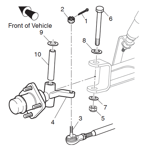
Remove cotter pin and loosen castellated nut until tie rod ball joint threads are protected. Using a ball articulation separator as a lever, apply pressure level to ball joint and tap nut with plastic faced hammer to release necktie rod from spindle arm. Remove nut from tie rod and tie rod from spindle arm. If removing passenger side spindle, echo previous step for rack brawl joint. Remove lock nut and washer from bolt and discard nut. Pull bolt and washer from spindle and split up spindle from axle. Remove thrust washer and king pin tube from spindle. Spindle installation is the contrary order of disassembly.
Tighten new lock nut to 56 – 70 ft. lbs. (75 – 95 Nm) torque. Check that spindle turns freely on king pin tube later tightening. Tighten castellated nut to 36 ft. lbs. (fifty Nm) torque and continue to tighten as needed to insert new cotter pin. Maximum torque is fifty ft. lbs. (70 Nm). Install front wheels and lower vehicle. Check front wheel alignment and adjust if necessary.
Rack and Pinion Unit Disassembly and Inspection
Remove rack and pinion unit from vehicle. Ballast in vice by clamping on the mounting ears of the unit. Disassemble rack and pinion unit past get-go removing screw and tensioner to save pressure on rack and pinion. Loosen jam nut and remove rack ball joint from rack extension. Cut wire ties securing bellows and slide bellows off rack extension. Pull rack from unit. Remove pinion seal. Remove internal retaining ring from rack and pinion unit and pull out pinion and ball begetting as an assembly.
Clean rack, pinion and housing. Inspect gear teeth, bearing surfaces and grease seal surfaces of rack and pinion for excessive article of clothing or damage. If any is found, the rack and pinion unit must exist replaced every bit an associates. If rack and pinion laissez passer inspection, clean them, tensioner and housing thoroughly and lubricate for associates.
Use grease specified in tool list. Assemble rack and pinion unit by offset installing pinion in reverse order of removal making sure to lubricate pinion seal lip prior to installing seal. Insert rack into rack and pinion unit. Turn pinion clockwise to aid pull rack in if necessary. Install bellows and secure to rack extension with wire necktie. Practice not secure big terminate of bellows to rack and pinion unit of measurement until instructed to do and then after setting proper rack extension-to-rack and pinion unit clearance.
Install tensioner and tighten bolts to 100 – 120 in. lbs. (11.5 – 13.8 Nm) torque. Thread jam nut and rack ball articulation to original location on rack extension and set jam nut hand tight. Install rack and pinion unit on vehicle.
Set proper rack extension-to-rack and pinion unit of measurement clearance.
Rack and Pinion Unit Replacement
To remove rack and pinion unit, loosen front end wheels and lift and support front of vehicle. Remove front wheels. Remove bolt and washer securing intermediate shaft to rack and pinion unit. Remove cotter pin and loosen castellated nut until rack ball articulation threads are protected. Using a ball articulation separator as a lever, apply pressure level to ball joint and tap nut with plastic faced hammer to release brawl articulation from passenger side spindle arm. Remove nut from brawl joint and ball articulation from spindle arm. Remove the three lock basics securing rack and pinion unit to front axle and discard basics. The rack and pinion unit can now be removed from vehicle. Retain washers, spacers and the ii bolts for assembly. Supersede rack and pinion unit of measurement in reverse order of removal. Employ new lock nuts and tighten them to 35 – 50 ft. lbs. (50 – 70 Nm) torque.
Tighten castellated nut to 36 ft. lbs. (50 Nm) torque and continue to tighten every bit needed to insert new cotter pin. Maximum torque is 50 ft. lbs. (70 Nm). Tighten commodities securing intermediate shaft to pinion to 155 – 215 in. lbs. (18 – 25 Nm) torque.
Prepare proper rack extension-to-rack and pinion unit clearance. Install forepart wheels and lower vehicle. Cheque front wheel alignment and adjust if necessary.
Checking/Adjusting Rack Extension-to-Rack and Pinion Unit Clearance
Check for proper rack extension-to-rack and pinion unit clearance by beginning turning steering wheel fully to the right. The rear spindle arm on the passenger side must balance confronting the front beam. If it does not, all adjustment is made at the rack ball articulation. Loosen jam nut at rack ball joint and use wrench to thread shaft of rack extension further into rack ball joint. This will provide more than travel for the steering wheel to exist turned to the correct.

With spindle arm resting against front beam, cut wire tie securing bellows to rack and pinion unit and slide bellows abroad from rack and pinion unit to run into large hex of rack extension. An 1/8″ gap should exist between the large hex and the end of the rack and pinion unit.
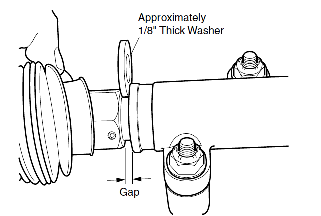
Adapt, using an i/8″ thick washer as a gauge, by turning shaft of rack extension with wrench to create the 1/8″ gap. Tighten jam nut to 35 – 45 ft. lbs. (47 – 61 Nm) torque. Secure bellows to rack and pinion unit with new wire tie.
Steering Bike Replacement
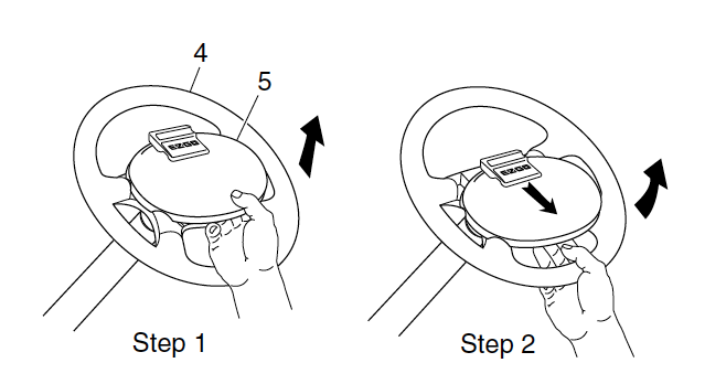
From the front side of the steering wheel, remove the clipboard by first pulling directly up on the bottom of the clipboard to release the ii bottom retaining tabs. Then, using thumb for leverage as shown, accomplish from behind steering wheel with fingertips to first pull down, and and so push up to release the two top clipboard retaining tabs.
Loosen the steering bike retaining nut two to three turns. Exercise Not REMOVE NUT AT THIS Fourth dimension. Apply upward pressure to the steering wheel. Place a plastic faced hammer against the steering bike nut and strike plastic faced hammer sharply with a ball peen hammer.
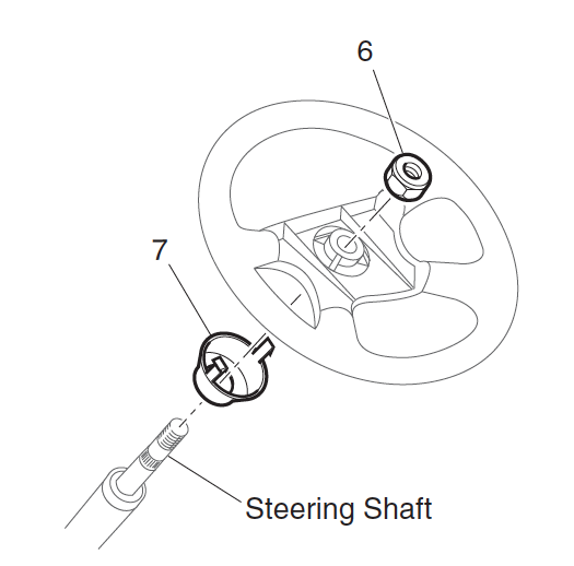
When steering wheel is loosened, remove retaining nut and remove steering wheel.
Prior to replacement, assemble the replacement steering wheel by adjustment the retaining tabs on the rear collar hub with slots in back of steering cycle. Clasp tabs to permit insertion of hub. Practise not strength. Clasp hub on peak and lesser to fully seat. Replace steering wheel by beginning lightly coating the splines of the steering shaft with a commercially available antiseize compound. With the vehicle wheels in the direct ahead position, align the steering bicycle on the steering shaft and slide bicycle on shaft. Tighten the steering wheel nut to 15 – xx ft. lbs. (20 – 27 Nm) torque.
Inspect the four retaining tabs on the clipboard for white stress lines. If stress lines are present, replace clipboard. Install by advisedly pressing, first the top two, and so the lesser two retaining tabs into the matching slots in steering wheel.
Steering Shaft and Column Replacement
To remove steering shaft remove the steering wheel. Loosen front wheels. Lift and support front of vehicle and remove front wheels. Remove the bolt and washer that secures the intermediate shaft to the steering shaft.
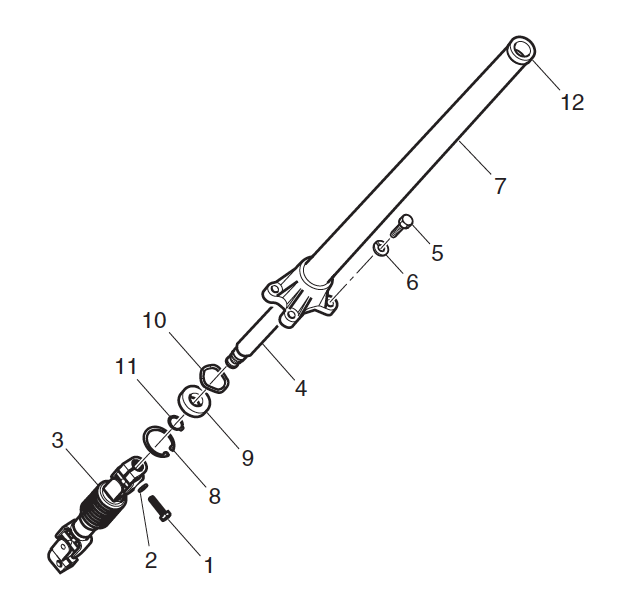
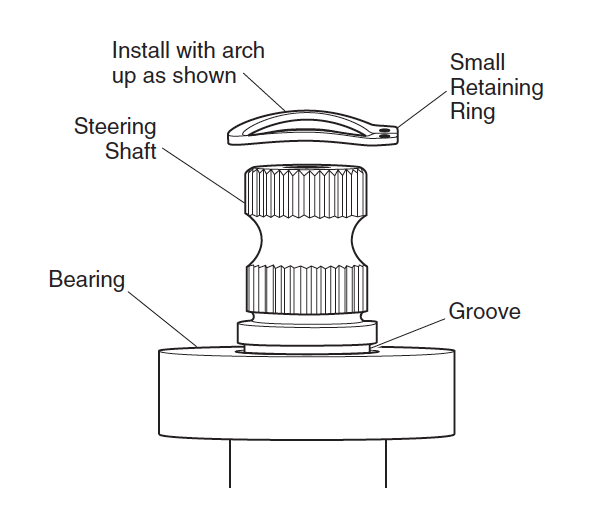
Remove the four bolts and washers that secure the steering column to the chassis and remove the column. Remove big retaining ring on lesser end of column and pull shaft and bearing out every bit an associates. Slide wave washer out bottom stop of steering cavalcade and keep for reuse. Remove small retaining ring and printing bearing from steering shaft. To get together steering shaft, first press new bearing onto shaft until it stops against shoulder. And then, with small retaining ring oriented with curvation up, slide band onto shaft as far as possible using snap ring pliers. Use fingers to push button retaining ring fully into groove.
Slide moving ridge washer into base of steering column. To install steering shaft and bearing associates, utilize cycle bearing grease to lip of seal in bushing at summit of column and press steering shaft and bearing assembly into column base of operations. Secure with big retaining ring making sure information technology is fully seated in groove of cavalcade. Place steering column on vehicle and tighten column bolts to 29 ft. lbs. (39 Nm) torque.
Tighten bolt securing intermediate shaft to steering shaft to 156 – 216 in. lbs. (xviii – 25 Nm) torque. Install front bicycle(s) and lower vehicle
Source: https://www.ezgogolfcartguide.com/repair-and-service-guides/front-suspension-and-steering/
Posted by: turkallynay.blogspot.com
0 Response to "How To Change King Pin On Front End Of An 2014 Ezgo Golf Car"
Post a Comment